S and S Machine
Quality First
Since 1973
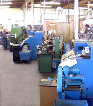
Our Machine Shop
Operation:
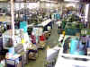 S and S Machine is an industrial machine shop which has been located in
Roseville, California (between Sacramento and Auburn just off Interstate 80) since
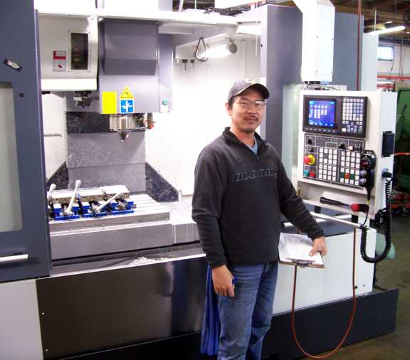
1973. More specifically, we are a CNC (computer numerically
controlled) job shop which means that we manufacture custom precision
machined parts to our customers specifications on computer controlled machine
tools. S and S Machine has about 25 employees and
over 30,000 square feet of combined shop, office and warehouse
space. We manufacture a wide range
of items such as medical equipment parts, functional test fixtures for the
electronics industry, aerospace parts, bicycle
parts, machinery parts and just about anything
else you can imagine that is machined from metal or plastic.
S and S Machine is an industrial machine shop which has been located in
Roseville, California (between Sacramento and Auburn just off Interstate 80) since
1973. More specifically, we are a CNC (computer numerically
controlled) job shop which means that we manufacture custom precision
machined parts to our customers specifications on computer controlled machine
tools. S and S Machine has about 25 employees and
over 30,000 square feet of combined shop, office and warehouse
space. We manufacture a wide range
of items such as medical equipment parts, functional test fixtures for the
electronics industry, aerospace parts, bicycle
parts, machinery parts and just about anything
else you can imagine that is machined from metal or plastic.
The History of S and S Machine:
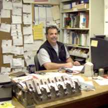
S and S Machine was founded by Steve Smilanick in 1973 in Roseville, CA.
It started as a job shop manufacturing a wide variety of custom machined components ranging from
specialty whirlpool parts to automotive transmission and engine adapters.
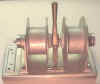 In 1976, we took on a partner and began to produce our own product, a line of commercial salmon fishing gurdies
(shown on the right without a motor) which led
the company to incorporate as S and S Commercial Fishing Equipment Inc. Fishing
gurdies are used on commercial salmon fishing boats to bring in the stainless
steel fishing lines. In 1980 the Pacific Coast Fishing Commission changed the laws that regulated commercial fishing which resulted in the reduction of the size of the salmon fleet and therefore a rapid decline in demand for gurdies. Soon after that decline, S and S discontinued the production of gurdies
and Smilanick bought out his partners half of the corporation but continued to do contract machining for our existing customers. We are still incorporated
in California as S and S Commercial Fishing Equipment Inc. but we are doing business as S and S Machine.
In 1976, we took on a partner and began to produce our own product, a line of commercial salmon fishing gurdies
(shown on the right without a motor) which led
the company to incorporate as S and S Commercial Fishing Equipment Inc. Fishing
gurdies are used on commercial salmon fishing boats to bring in the stainless
steel fishing lines. In 1980 the Pacific Coast Fishing Commission changed the laws that regulated commercial fishing which resulted in the reduction of the size of the salmon fleet and therefore a rapid decline in demand for gurdies. Soon after that decline, S and S discontinued the production of gurdies
and Smilanick bought out his partners half of the corporation but continued to do contract machining for our existing customers. We are still incorporated
in California as S and S Commercial Fishing Equipment Inc. but we are doing business as S and S Machine.
The surplus machining capacity resulting from the loss of the gurdie business was quickly absorbed by our job shop operations. At that time, S and S also built it’s first building of 4000 square feet. Since then, we have continued to expand our contract machining capabilities by adding more customers, machines and employees.
 A major turning point for S and S came in about 1981 as a result of our involvement with Shugart Associates, a computer floppy disk drive manufacturer, in
Roseville. We manufactured a wide variety of tools and fixtures to print for their disk drive assembly line and we also worked with their engineers on the design and manufacture of special custom tools and test fixtures. One of our greatest accomplishments for Shugart was to design and build a head test and adjustment fixture that was built
instead of a proposed twenty thousand dollar tool of their design. The tool that we designed cost only three thousand dollars but better yet, was done in only 3 days instead of the 4 to 6 weeks that would have been required if we had done the job as proposed by them. With the use of that tool, they were able to reduce their rejection rate of finished drives from 95% failure rate (they had to assemble each drive to find out if the head was
good or bad) to almost 0% due to bad heads. With approximately 300 workers at their plant assembling those drives, and
with a 95% failure rate at final inspection, they were in big trouble without a test fixture that could
inspect and repair a head before it was installed in the drive. When Shugart later closed their Roseville plant, the engineers that we did design work for moved to other companies and took us with them as a supplier. That quickly broadened our customer base which resulted in a major increase in our work load. By 1986, we had outgrown our building so we purchased
the 17,000 sq ft building where we are currently located.
A major turning point for S and S came in about 1981 as a result of our involvement with Shugart Associates, a computer floppy disk drive manufacturer, in
Roseville. We manufactured a wide variety of tools and fixtures to print for their disk drive assembly line and we also worked with their engineers on the design and manufacture of special custom tools and test fixtures. One of our greatest accomplishments for Shugart was to design and build a head test and adjustment fixture that was built
instead of a proposed twenty thousand dollar tool of their design. The tool that we designed cost only three thousand dollars but better yet, was done in only 3 days instead of the 4 to 6 weeks that would have been required if we had done the job as proposed by them. With the use of that tool, they were able to reduce their rejection rate of finished drives from 95% failure rate (they had to assemble each drive to find out if the head was
good or bad) to almost 0% due to bad heads. With approximately 300 workers at their plant assembling those drives, and
with a 95% failure rate at final inspection, they were in big trouble without a test fixture that could
inspect and repair a head before it was installed in the drive. When Shugart later closed their Roseville plant, the engineers that we did design work for moved to other companies and took us with them as a supplier. That quickly broadened our customer base which resulted in a major increase in our work load. By 1986, we had outgrown our building so we purchased
the 17,000 sq ft building where we are currently located.
Over the years, we have found that design work and cost reduction continue to be one of our major strengths. For the last 15 years, we have offered extensive design assistance to our customers in the high tech industries. On a regular basis, we manufacture complex assembly and
test fixtures for
electronics companies and we have had as many as 57 fixtures in progress at the same time.
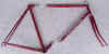
 In addition to our contract machine work, in 1993, we designed and developed a
bicycle frame tube coupling device for the bicycle industry
which is now used by over 100 bicycle framebuilders around the world. The coupling is called an S and S Bicycle Torque Coupling™
(BTC™). BTCs are used by world class cyclists like
Greg LeMond as well as frequent flyers who just want to take their favorite bicycle with them when they travel. BTCs allow a cyclist to pack a full size bicycle in an airline legal case that measures only 26x26x10” (see us at
https://sandsmachine.com). The coupling has also revolutionized bicycle design by making it possible to make convertible bicycles which can be assembled into multiple configurations. The most radical convertible made so far is a
Ventana tandem to quint convertible. It can be configured to accommodate two, three, four or five riders.
In addition to our contract machine work, in 1993, we designed and developed a
bicycle frame tube coupling device for the bicycle industry
which is now used by over 100 bicycle framebuilders around the world. The coupling is called an S and S Bicycle Torque Coupling™
(BTC™). BTCs are used by world class cyclists like
Greg LeMond as well as frequent flyers who just want to take their favorite bicycle with them when they travel. BTCs allow a cyclist to pack a full size bicycle in an airline legal case that measures only 26x26x10” (see us at
https://sandsmachine.com). The coupling has also revolutionized bicycle design by making it possible to make convertible bicycles which can be assembled into multiple configurations. The most radical convertible made so far is a
Ventana tandem to quint convertible. It can be configured to accommodate two, three, four or five riders.
Company Philosophy:
-
We take great pride in delivering quality parts
on time at a
competitive price.
-
We always look for ways to improve the performance and
reliability of a part.
-
We are dedicated to cost reduction through improved efficiency
and part simplification.
-
We work hard to develop and maintain long term relationships
with our customers.
-
We know that our success is dependent on the success of our
customers.
Quality:
 |
S and S Machine is committed to quality. We have always taken great pride in meeting customer requirements regarding strict adherence to stated print tolerances but it doesn't stop there.
We frequently go beyond the print and examine a parts function to ensure that the part will fit to it's mating part and function as it was intended to.
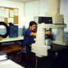
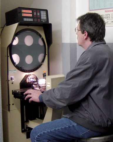
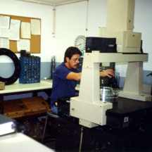
Our quality assurance department is staffed by highly trained and experienced personnel and is equipped with state of the art inspection equipment. This department utilizes two coordinate measuring machines,
three optical comparators, and a wide variety of sophisticated measuring
instruments
(click here to view our inspection
department's equipment list).
All quality assurance equipment is kept in top working condition and is calibrated and traceable to the National Bureau of Standards in accordance with
our quality assurance manual. Most of S and S Machine’s employees have been formally trained in statistical process control and implements it when required by the customer or the quality assurance department. For these reasons,
we maintain the highest level of quality with all
of our customers.
|
 |
| |
|
|
On Time Delivery:
 |
S and S is committed to on time delivery. Meeting customer "just in time" delivery requirements has always been one of
our company’s primary strengths. We attempt to limit the amount of work booked to about 70 percent of
our maximum production capacity (maximum capacity uses 30 - 85% of all available overtime depending on the type of work being done). By resisting the temptation to book more work,
we maintain a comfortable workload yet they have the flexibility to allow for unexpected orders required to meet their customers' emergency requirements. S and S Machine utilizes a simple but effective scheduling system to track work through the shop and to monitor final delivery dates. The system is easily accessed and modified in the event that a customer wants to change a single delivery date or the entire delivery schedule. The system is monitored by manufacturing, administration and shipping to ensure on time deliveries. Especially on repeat parts, it has always been
our policy to run a few more parts than are required to meet the actual order quantity.
The extra parts make up for parts that could be damaged in production, outside processing or shipping and if not needed for those reasons, are
labeled with the part number and revision letter then put into inventory to fill future orders or to meet our customers unexpected requirements.
We have always been very flexible with our customers' changing delivery date requirements and
we make every effort to accommodate changes. In addition to the internal controls,
we have developed a reliable network of suppliers and sub contractors that understand our philosophy of on time delivery. Those suppliers are critical to our
success.
|
 |
Pricing:
Our pricing is based on a formula that uses variables including production quantity, hourly shop rate, actual part run time,
material cost, and subcontractor costs. We take all of those factors into consideration to establish the price of a part.
Our hourly shop rates are as follows: manual
machine work = $120.00/hour, CNC machine work = $150.00/hour; CAD services =
$120.00/hour, inspection services = $120.00/hour, Mazak Mulitplex CNC machine work =
$150.00/hour.
Cost Reduction:
 S and S Machine is committed to cutting costs through improved efficiency
and part simplification. We hate waste and love a challenge. We frequently
see details on parts that don't make sense from a manufacturing perspective or
a tolerance that seems too tight. When that happens, we will very likely call
the purchasing agent or engineer and discuss the issue. Here are two examples
of parts we improved significantly.
S and S Machine is committed to cutting costs through improved efficiency
and part simplification. We hate waste and love a challenge. We frequently
see details on parts that don't make sense from a manufacturing perspective or
a tolerance that seems too tight. When that happens, we will very likely call
the purchasing agent or engineer and discuss the issue. Here are two examples
of parts we improved significantly.
 Example 1. We were making a precision rack for a
customer for about a year but we were having problems holding the tolerances
because the raw investment castings they provided were warped up to
.040" and the print called for only .005" tolerance. We
brought the problem to the attention of our customer and they wouldn't change
the investment casting tooling since the parts we made were working yet they
wouldn't change the print to accept a looser tolerance. At that point, we
decided to quit making the part. A few months later they came back to us with
a truck load of that parts that another machine shop made that wouldn't work in
their machine. We reworked the other shop's parts and made them useable but they were
still not to print. A year or so later, we redesigned the part and not only reduced the weight and improved
its reliability, but it dropped the cost from $457.00 each to about $150.00. At the time,
their monthly usage was 500 parts which resulted in a cost savings of over $150,000 per
month and we have been building that part now for over15 years.
Example 1. We were making a precision rack for a
customer for about a year but we were having problems holding the tolerances
because the raw investment castings they provided were warped up to
.040" and the print called for only .005" tolerance. We
brought the problem to the attention of our customer and they wouldn't change
the investment casting tooling since the parts we made were working yet they
wouldn't change the print to accept a looser tolerance. At that point, we
decided to quit making the part. A few months later they came back to us with
a truck load of that parts that another machine shop made that wouldn't work in
their machine. We reworked the other shop's parts and made them useable but they were
still not to print. A year or so later, we redesigned the part and not only reduced the weight and improved
its reliability, but it dropped the cost from $457.00 each to about $150.00. At the time,
their monthly usage was 500 parts which resulted in a cost savings of over $150,000 per
month and we have been building that part now for over15 years.
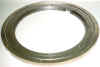 Example 2. Another trouble part we redesigned was a 21 inch diameter
Mic-6 aluminum instrument ball bearing with plastic
(Delrin) balls
(21" sounds big for an instrument but it has a robot that works in the
open bearing bore which is why it has to be so big) It had a very high failure
rate and when it failed, it not only destroyed the test samples loaded in the
instrument causing
unacceptable delays and loss of revenue but a technician had to be flown
to the site to completely disassemble the complex instrument to replace the
bearing. That process tied up a technician for at least two days and cost
thousands of dollars. We were familiar with the problem that they were having
with the old non adjustable bearing so we suggested an alternative design that
would allow for adjustment of the bearing during regular servicing of the machine
and looser manufacturing tolerances. We received an order for a prototype of
our new design. Once the prototype was tested and approved by our customer, we
received a contract to produce them and we have made thousands of them since
then. We not only reduced the cost of the bearing due to a design that allowed
for looser manufacturing tolerances, but over the10 plus years of using the new
bearing, not a single bearing has failed or needed replacing.
Example 2. Another trouble part we redesigned was a 21 inch diameter
Mic-6 aluminum instrument ball bearing with plastic
(Delrin) balls
(21" sounds big for an instrument but it has a robot that works in the
open bearing bore which is why it has to be so big) It had a very high failure
rate and when it failed, it not only destroyed the test samples loaded in the
instrument causing
unacceptable delays and loss of revenue but a technician had to be flown
to the site to completely disassemble the complex instrument to replace the
bearing. That process tied up a technician for at least two days and cost
thousands of dollars. We were familiar with the problem that they were having
with the old non adjustable bearing so we suggested an alternative design that
would allow for adjustment of the bearing during regular servicing of the machine
and looser manufacturing tolerances. We received an order for a prototype of
our new design. Once the prototype was tested and approved by our customer, we
received a contract to produce them and we have made thousands of them since
then. We not only reduced the cost of the bearing due to a design that allowed
for looser manufacturing tolerances, but over the10 plus years of using the new
bearing, not a single bearing has failed or needed replacing.
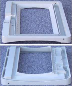
 Example
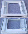
3.This
a top and bottom view of a plastic molded part that we made a
machined aluminum replacement for. We stumbled onto this job
when I happened to be visiting our customer's facility regarding another
part and I was invited into the purchasing directors office. While
there, the director had a discussion with an engineer regarding this
part and how poor the quality was and the trouble it was
causing by delaying the delivery of their machines. He told me how
expensive it was and how much trouble he was having getting good parts. I
suggested that if he couldn't find a vendor that could produce a good
part and if production was being delayed, he might want to consider a temporary
measure of having it machined from aluminum plate. I told him that I thought
we could do it for about the same as the molded part and that I could
guarantee
he wouldn't have trouble with the part breaking. We got and order the next
day and as it turned out, we made hundreds of those parts until the
machine went out of production several years later and we never had a failure
or problem of any kind. We did it for about the same price or slightly less than
the original plastic part but they saved overall due to it's
reliability. This is a great
example of why we like to be locate close to our customers so we can
get involved if a problem arises..
Example
3.This
a top and bottom view of a plastic molded part that we made a
machined aluminum replacement for. We stumbled onto this job
when I happened to be visiting our customer's facility regarding another
part and I was invited into the purchasing directors office. While
there, the director had a discussion with an engineer regarding this
part and how poor the quality was and the trouble it was
causing by delaying the delivery of their machines. He told me how
expensive it was and how much trouble he was having getting good parts. I
suggested that if he couldn't find a vendor that could produce a good
part and if production was being delayed, he might want to consider a temporary
measure of having it machined from aluminum plate. I told him that I thought
we could do it for about the same as the molded part and that I could
guarantee
he wouldn't have trouble with the part breaking. We got and order the next
day and as it turned out, we made hundreds of those parts until the
machine went out of production several years later and we never had a failure
or problem of any kind. We did it for about the same price or slightly less than
the original plastic part but they saved overall due to it's
reliability. This is a great
example of why we like to be locate close to our customers so we can
get involved if a problem arises..
Click here for a
close-up view of the defects in the molded part and a comparison
to the new part..
Problems with the original bezel:
-
The edge of the bezel was pitted which
caused leakage at the gasket.
-
Fine edges would break off.
-
Screw bosses would break off.
-
There were also lots of pinholes everywhere.
-
The plastic bezel was prone to cracking at the
corners after being delivered to the customer.
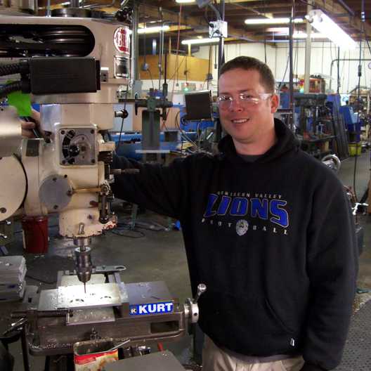
Parts Made by S and S Machine:
Functional
Test Fixtures for the Electronics Industry
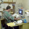
 We design and build a wide variety of functional
test fixtures for the electronics industry. A design might take from
1 to 3 weeks to complete plus an additional 2 to 6 weeks to produce
the actual fixture. If multiple fixtures are being made, we
typically make all the parts at once but we only assemble the first
fixture to test the design. Normally the fixtures work as planned
and there are very few if any modifications to the original design
required.
We design and build a wide variety of functional
test fixtures for the electronics industry. A design might take from
1 to 3 weeks to complete plus an additional 2 to 6 weeks to produce
the actual fixture. If multiple fixtures are being made, we
typically make all the parts at once but we only assemble the first
fixture to test the design. Normally the fixtures work as planned
and there are very few if any modifications to the original design
required.
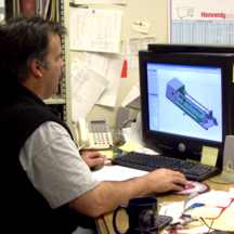
All of our fixtures are designed on AutoDesk Inventor so we can test the fixture in a 3D model on the
computer before we start machining.
We build very simple
fixtures which might be designed to test a small peripheral device
such as a video card or other small circuit board while it's
connected to a larger device such as a computer. A typical simple fixture
might plug the video card into the PCI slot on a computer to verify
the video cards functionality.
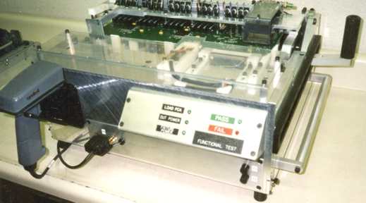
A more complex test fixture might
test a motherboard. When testing a motherboard, all peripheral
devices and components necessary to make a fully
functional computer need to be connected with as little as a single
lever movement. The items typically connected to the motherboard include the CPU, monitor, video card, modem, network card,
power supply, hard drive, floppy drive, CD drive plus every input or
output connector must be connected to the motherboard. Once the
devices are connected, the board is automatically powered up and run
through a series of functional tests to verify it's performance. At
S and S Machine, we typically do the mechanical portion of the fixture, not the
electronics or software.
|
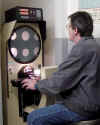
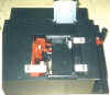
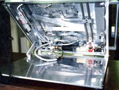
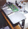 In
this example, a fixture is mounted on top of a computer chassis that
was modified to accept the fixture. An extender board is mounted in
the PCI slot of the computer and the device being tested is
automatically plugged into the extender board. Using an extender not
only makes it easy to access the motherboard, but it also is cheaper
to replace the extender board rather than the computer mother board
when the PCI slot contacts get worn out from all the use it gets
plugging the cards in and out.. In
this example, a fixture is mounted on top of a computer chassis that
was modified to accept the fixture. An extender board is mounted in
the PCI slot of the computer and the device being tested is
automatically plugged into the extender board. Using an extender not
only makes it easy to access the motherboard, but it also is cheaper
to replace the extender board rather than the computer mother board
when the PCI slot contacts get worn out from all the use it gets
plugging the cards in and out..
|
|
 This fixture has the ability to hold many different sizes and shapes of cards. When the actuation lever is moved, the card advances towards a adaptor card that is loaded into a vacant expansion slot in a pc. This fixture has the ability to hold many different sizes and shapes of cards. When the actuation lever is moved, the card advances towards a adaptor card that is loaded into a vacant expansion slot in a pc.
|
|
 Getting away from using a modified computer chassis as the base for the
fixture, this is a simple method of accessing the board being tested
from all sides. Getting away from using a modified computer chassis as the base for the
fixture, this is a simple method of accessing the board being tested
from all sides.
|
|
 With this fixture, the unit under test is set in a nest that is stationary. The connectors and hold downs move from each side to engage the card. The last motion of the hand lever brings a probe plate up from the bottom to contact test points located on the bottom of the card. With this fixture, the unit under test is set in a nest that is stationary. The connectors and hold downs move from each side to engage the card. The last motion of the hand lever brings a probe plate up from the bottom to contact test points located on the bottom of the card.
|
|
 This fixture has two different test bays for testing two different
types of cards. It has a "keep out plate" so only one type of card can be tested at a time.
The white "keep out plate" flips from one side to the other
and prevents more than one card being inserted at a time. When the lever is actuated, the card moves into a
modified computer cassis and the test is performed. This fixture has two different test bays for testing two different
types of cards. It has a "keep out plate" so only one type of card can be tested at a time.
The white "keep out plate" flips from one side to the other
and prevents more than one card being inserted at a time. When the lever is actuated, the card moves into a
modified computer cassis and the test is performed.
|
|
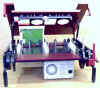
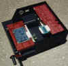
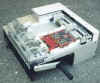
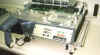
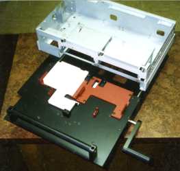
   This is a bit of an unusual test fixture in that our customer wanted
to be able to stack as many fixtures high and wide as was necessary to
keep the operator busy loading and unloading boards while other boards
were being tested. The board being tested was placed in the drawer and
when the drawer was closed, it plugged the card into a system board
(not shown here) that was located in the empty area in the middle of
the fixtures. It also automatically scanned two barcodes with a
barcode reader that was moved by a solenoid to each barcode
label. The first two photos show drawer open and closed. The
second and third photos have the cover removed to show the inside. The
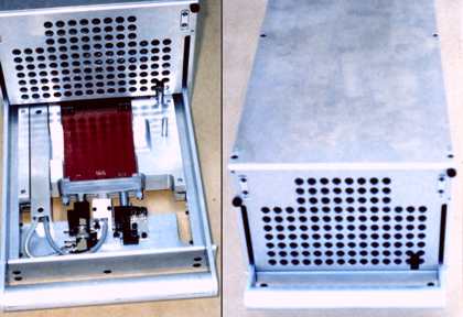
open space in the middle is where the system board will go. This is a bit of an unusual test fixture in that our customer wanted
to be able to stack as many fixtures high and wide as was necessary to
keep the operator busy loading and unloading boards while other boards
were being tested. The board being tested was placed in the drawer and
when the drawer was closed, it plugged the card into a system board
(not shown here) that was located in the empty area in the middle of
the fixtures. It also automatically scanned two barcodes with a
barcode reader that was moved by a solenoid to each barcode
label. The first two photos show drawer open and closed. The
second and third photos have the cover removed to show the inside. The
open space in the middle is where the system board will go.
|
|
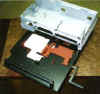
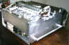
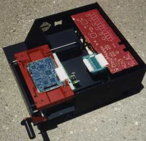
 When fixture lever is actuated, the board is grabbed with fingers
from the side to hold the card down. Then, a probe plate comes up from
the bottom to electrically probe board as the board moves forward to
engage the system board. It is shown here with the cover removed.
Normally, only the lower red portion next to the hand lever is
exposed. When fixture lever is actuated, the board is grabbed with fingers
from the side to hold the card down. Then, a probe plate comes up from
the bottom to electrically probe board as the board moves forward to
engage the system board. It is shown here with the cover removed.
Normally, only the lower red portion next to the hand lever is
exposed.
|
|
 With this fixture, the card under test is stationary and all the plug on and test points come to the card. The action is from the front, back and top. With this fixture, the card under test is stationary and all the plug on and test points come to the card. The action is from the front, back and top.
|
|
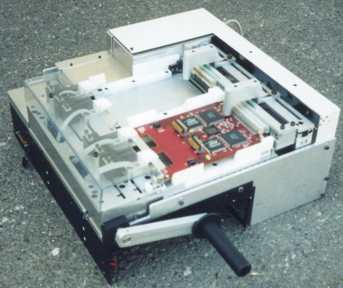
   In
this fixture, the card under test is placed in a nest in the center,
as the lever is actuated the nest and a front slide loaded with
connectors and probes move towards the system board at different rates
so that all the probes and connectors plug to the card under test at
the same time. The last part of the action is to bring a plate down
from the top to probe test points on the top of the board. All of
those actions are accomplished with the movement of one lever. In
this fixture, the card under test is placed in a nest in the center,
as the lever is actuated the nest and a front slide loaded with
connectors and probes move towards the system board at different rates
so that all the probes and connectors plug to the card under test at
the same time. The last part of the action is to bring a plate down
from the top to probe test points on the top of the board. All of
those actions are accomplished with the movement of one lever.
Fixture opened to show the mechanical
workings, view from the back and front view.
|
|
  This is an extra large six axis fixture. It measures over 4 feet tall and
instead of sitting on a table, it sits directly on the floor. With a single lever action, the fixture brings the
system board under test into a back plane board then stripper rods come up from the bottom and down from the top to sandwich the board in place. Next, the components are inserted from the top, bottom and left side. The weight of the components that rise from the bottom
are over 150 lbs. Once all of the components are connected or probed,
the system is automatically booted up and the board is tested. This fixture can be locked in the open
or closed position electrically. Again this is all done with a single lever that can be easily actuated by one hand.
3D CAD models like the one shown here are made and tested before we begin
production. This is an extra large six axis fixture. It measures over 4 feet tall and
instead of sitting on a table, it sits directly on the floor. With a single lever action, the fixture brings the
system board under test into a back plane board then stripper rods come up from the bottom and down from the top to sandwich the board in place. Next, the components are inserted from the top, bottom and left side. The weight of the components that rise from the bottom
are over 150 lbs. Once all of the components are connected or probed,
the system is automatically booted up and the board is tested. This fixture can be locked in the open
or closed position electrically. Again this is all done with a single lever that can be easily actuated by one hand.
3D CAD models like the one shown here are made and tested before we begin
production.
|
Aerospace
and Military
Parts and Support Tooling
Although we have done aerospace parts in the past, we now stick
to aerospace tooling rather than parts that fly. The documentation aspect of
aerospace parts can be more demanding that making the actual part not to mention
the added cost of insurance to do that type of work. Since compared to our
commercial work, aerospace parts were such a small percentage of what we did, we
decided to no longer bid those jobs. Tooling on the other hand, is also
interesting and challenging but since it doesn't fly, it usually doesn't require
extensive documentation so we continue to take those jobs when they are
available..
We are a
DDTC registered
Exporter/Manufacturer.
All manufacturers, exporters, and brokers of defense articles,
defense services, or related technical data, as defined on the United
States Munitions List, are required to register with Directorate of
Defense Trade Controls DDTC.
Special Purpose
Machines or Devices
These devices aren't specific to any industry. They might be a
testing, manufacturing, measuring or processing device that could be form just
about any field from medical science to manufacturing. We have made soil
sampling tools, chemical weighing devices, surgical devices, calibration
devices, special tools, internal combustion engines, automated test equipment,
materials handling devices, assembly tooling, work holding devices and a myriad
of other things that fall into this category. Unfortunately, most of those
devices involve patents or trade secrets so they can't be shown here.
|
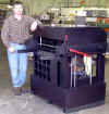
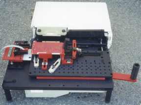
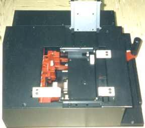
   Turning machine: This is a special purpose turning machine that we made for
one of our customers. As with most for the devices that we make, it was designed on our CAD system so it could be tested before we began
production. Turning machine: This is a special purpose turning machine that we made for
one of our customers. As with most for the devices that we make, it was designed on our CAD system so it could be tested before we began
production.
|
|
  Dental
implant testing machine: This machine was designed and manufactured at
S and S Machine for Dr. Paul
Binon who was doing research regarding the
life expectancy of dental implants as a function of implant manufacturing
tolerances. It combines vertical movement, that represents the
force of chewing, with a circular motion, so the chewing load is applied
at different places on the abutment (top) of the implant, each time the
pin comes down. By combining a vertical and circular motion, it more
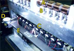
closely simulates chewing. Dental
implant testing machine: This machine was designed and manufactured at
S and S Machine for Dr. Paul
Binon who was doing research regarding the
life expectancy of dental implants as a function of implant manufacturing
tolerances. It combines vertical movement, that represents the
force of chewing, with a circular motion, so the chewing load is applied
at different places on the abutment (top) of the implant, each time the
pin comes down. By combining a vertical and circular motion, it more
closely simulates chewing.
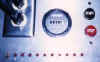
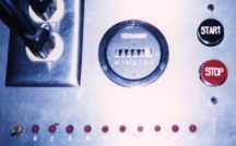
The tooth is mounted in the black block labeled C. All ten
blocks are mount on a horizontal bar, labeled E, that moves slowly in
circular motion in a horizontal plane. The vertical force comes from a pin
that is spring mounted in a piston, labeled B, that is driven down by the
camshaft, labeled A, as it rotates. The piston moves back up under spring
pressure when the cam rotates away from the piston. The piston has a
roller mounted on the top to extend the life of the cams. To detect wear,
an electrical probe is set to a precise distance from the abutment. That
distance setting or gap is set by using a dial indicator and an indicator
light. The gap is set by first bringing the probe into contact with the
abutment being tested which completes a low voltage electrical circuit.
Then, the probe is moved away from the abutment until the circuit is
broken. Then, the probe is adjusted to a specific distance (the specified
gap) away from the abutment with the dial indicator, labeled D. The
indicator can be slid along the front bar, labeled E, to setup the other
implants for testing. When the implant wears out due to screw loosening,
the abutment portion of the implant begins to rock from side to
side. When it rocks enough to bridge the gap and touch the electrical
probe momentarily, it completes the electrical circuit and stops the
machine. By recording the meter reading, in minutes, for each implant's
start and finish time, it is possible to calculate the exact life of
each implant in cycles, even though the machine is starting and stopping
as different implants fail. When an implant fails, a light indicates
which implant failed. Once a new implant that needs testing has been put
into the machine and adjusted, the reset button is pressed and testing is
resumed. The meter is never reset to zero so it's easy to keep track of
start and stop times for each implant. |
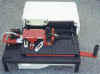
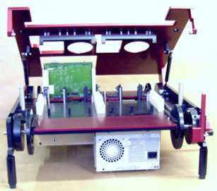
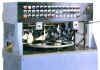 Eddy
current test machine. This testing machine was designed to detect
cracks is aluminum discs that were being machined on a production basis.
The machine has an indexable platen with three wells that each accept one
part. A part is loaded at station 1 then the platen indexes the part to
station 2 where eddy current test probes move back and forth across the
top and bottom of the disc while it spins. Once the test is completed, the
platen indexes to station 3 where rejected parts automatically ejected.
Good parts come back to the loading station, station one, and are manually
removed and a new part is loaded for testing. We built this machine from
top to bottom for our customer who did the design work in phases as we
built parts. Although we weren't responsible for the overall design, we
did assist their engineer on many parts to make them easier to
manufacture. This machine sits on the floor and is about 6 feet tall. Most
of the mechanical parts are located in the cabinet below the platen. Eddy
current test machine. This testing machine was designed to detect
cracks is aluminum discs that were being machined on a production basis.
The machine has an indexable platen with three wells that each accept one
part. A part is loaded at station 1 then the platen indexes the part to
station 2 where eddy current test probes move back and forth across the
top and bottom of the disc while it spins. Once the test is completed, the
platen indexes to station 3 where rejected parts automatically ejected.
Good parts come back to the loading station, station one, and are manually
removed and a new part is loaded for testing. We built this machine from
top to bottom for our customer who did the design work in phases as we
built parts. Although we weren't responsible for the overall design, we
did assist their engineer on many parts to make them easier to
manufacture. This machine sits on the floor and is about 6 feet tall. Most
of the mechanical parts are located in the cabinet below the platen. |
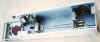
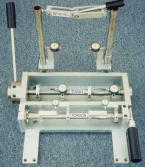
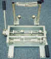 Torsion, tension
and bending test fixture. We built this fixture to demonstrate that a
frame tube with our a Bicycle Torque Coupling installed in it is stronger
in torsion, tension and bending than an equivalent length section of tube
without a coupling. Torsion, tension
and bending test fixture. We built this fixture to demonstrate that a
frame tube with our a Bicycle Torque Coupling installed in it is stronger
in torsion, tension and bending than an equivalent length section of tube
without a coupling.
For more details regarding its function and
the test results, visit our Bicycle Torque Coupling web site by clicking
here |
|
 This fixture brings a set of probes down and compresses them against contacts on the unit under test, it also applies a load to torque the board during the test. This helps check for opens or shorts in the traces of the board. This fixture brings a set of probes down and compresses them against contacts on the unit under test, it also applies a load to torque the board during the test. This helps check for opens or shorts in the traces of the board.
|
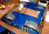 BattleBot
We built the gearbox and motor mounts for this BattlBot. Click the
image for more photos of the parts we made, some battle action shots and a link to the BattleBot web site. BattleBot
We built the gearbox and motor mounts for this BattlBot. Click the
image for more photos of the parts we made, some battle action shots and a link to the BattleBot web site.
|
|
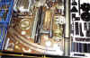
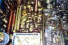
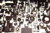
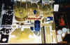
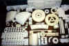
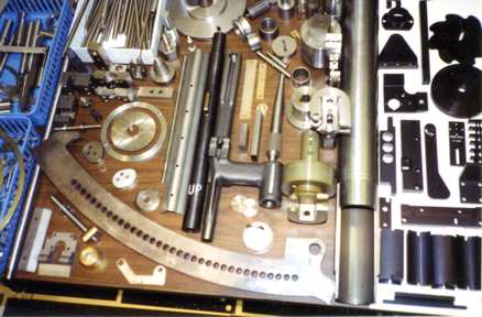
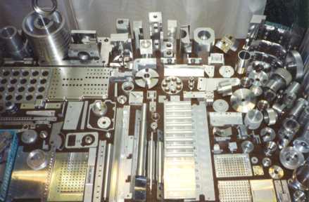
Miscellaneous Parts
The following are just a few of the parts that we have made over the years
and they can be found in just about any industry that you can imagine.
They fit into medical equipment, scientific instruments, electronic
devices, construction tools, lasers, business machines, plumbing
devices, prosthetic devices, exercise equipment, robots, fixtures, hand
tools, specialized power
tools, well drilling and monitoring equipment and more. We quit taking
photos of parts groupings like this about 10 years ago so you can
imagine, this is only a small sampling of what we have done.
|
 |
 |
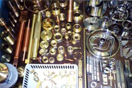
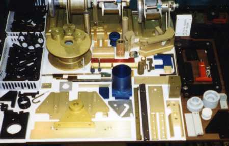
| Steel, stainless steel and black anodized
parts. |
Brass, copper, titanium and stainless
steel |
|
|
|
 |
 |
| Black anodize aluminum parts |
Painted or anodized aluminum. |
|
|
|
 |
 |
| PTFE,
Delrin,
polyethylene and G10 |
Aluminum parts (no finish) |
|
|
|
|
See the table below for 250 more miscellaneous parts
|
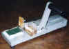
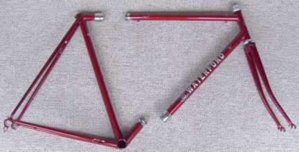
Bicycle
Torque Couplings
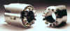 We also have a product of our own called a BTC (Bicycle Torque
Coupling). BTCs were invented and are produced at S and S Machine. A full size bicycle
with BTCs installed can be taken apart and packed into a case
that travels as regular airline luggage. This coupling was the result
of Steve Smilanick's passion for cycling and his desire
to take his bike with him on a Mediterranean cruise. We make BTCs out
of several materials including: 17-4 PH stainless steel, 304 stainless, 7005
aluminum, 6AL/4V titanium and chrome-moly steel. The coupling in the
photo on the right is
made from 17-4 PH stainless steel. All of our couplings are machined from
solid bar stock on a Mazak Multiplex CNC machine tool. The Mazak combines two
lathe spindles with milling capabilities to efficiently produce highly accurate
parts. That machine makes nothing but couplings every day, all year round.
We also have a product of our own called a BTC (Bicycle Torque
Coupling). BTCs were invented and are produced at S and S Machine. A full size bicycle
with BTCs installed can be taken apart and packed into a case
that travels as regular airline luggage. This coupling was the result
of Steve Smilanick's passion for cycling and his desire
to take his bike with him on a Mediterranean cruise. We make BTCs out
of several materials including: 17-4 PH stainless steel, 304 stainless, 7005
aluminum, 6AL/4V titanium and chrome-moly steel. The coupling in the
photo on the right is
made from 17-4 PH stainless steel. All of our couplings are machined from
solid bar stock on a Mazak Multiplex CNC machine tool. The Mazak combines two
lathe spindles with milling capabilities to efficiently produce highly accurate
parts. That machine makes nothing but couplings every day, all year round.
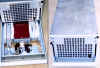
 The photo on the left, shows how a frame equipped with BTCs separates so it
will fit into a case that travels as regular airline luggage. In addition
to single bikes, tandem bicycles can also be fit with couplings so they fit into
the same size case or cases. Some
bicycle framebuilders even make bicycles that can be assembled in different
configurations to handle anywhere from two to five riders. They are
called convertibles
and they are a completely new class of bicycles made possible by BTCs.
The photo on the left, shows how a frame equipped with BTCs separates so it
will fit into a case that travels as regular airline luggage. In addition
to single bikes, tandem bicycles can also be fit with couplings so they fit into
the same size case or cases. Some
bicycle framebuilders even make bicycles that can be assembled in different
configurations to handle anywhere from two to five riders. They are
called convertibles
and they are a completely new class of bicycles made possible by BTCs.
Capabilities:
S and S Machine is a comprehensive industrial manufacturing resource for our customers.
Our services are very diverse and we continue to expand our capabilities.
We focus on jobs that involve primarily industrial machine work but we are capable of
doing additional processes as well. We commonly do fabrication, sheet
metal work, design work or any other services that are required to meet the needs of our customers. Our
production quantities range from one part to over a thousand. Most runs range from
twenty to two hundred pieces.
-
Machining processes: 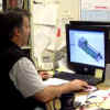 Precision machining, manual turning,
manual milling, CNC turning, CNC milling, surface grinding, contour
sawing, bandsawing, gear cutting, boring and drilling.
Precision machining, manual turning,
manual milling, CNC turning, CNC milling, surface grinding, contour
sawing, bandsawing, gear cutting, boring and drilling.
-
Fabrication processes: Welding, bending, forming, punching,
grinding and sawing.
-
Sheet metal process: Stamping, shearing, bending, punching,
notching, welding,
-
Services: Assembly, calibration, inspection, mechanical drawings,
CAD drawings, design work assistance, heat treating, digitizing,
invention
development, product development and manufacturing engineering (process
improvement).
-
Outside processes: water jet cutting, plasma cutting,
laser jet cutting,
-
Typical parts: Functional test fixtures, tooling, prototypes,
industrial models, instrument parts, medical equipment parts, bicycle parts,
robot parts, prosthetic parts, tools, special purpose machines, molds,
electronic enclosures, test equipment, sampling devices, material handling
equipment, jigs and fixtures, drill jigs, assembly tooling, templates, inspection
tooling, compression molds, machinery, instrumentation, stamping dies,
welding fixtures and electronics tooling.
-
Things we don't do: We don't do automotive
suspension, steering, power train or engine work for consumers. We have
done automotive parts on a production basis.
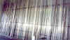
| The photo shows one of two of our stock racks which are each 40
feet long. In this rack, we maintain a basic inventory of 6061 T6
bar stock in flat, square and round so we can respond quickly to our
customers needs. Our second rack has all the basic sizes of cold
finished 1018 mild steel in flat, square and round plus an assortment of
303, 304 and 17-4 PH stainless steel, Stressproof and free machining
brass. In another area, we keep an assortment of plastics such as Delrin,
nylon and UHMW. We also maintain a modest inventory of tool steel. |
 |
-
Materials used:
-
Aluminum alloys:
1100,1145, QC-10 ALLOY, 1235, 2007, 2011 2017, 2025, 3003, 3105,
4042, 5052, 5083, 5086, 6013, 6020, 6060, 6061, 6063, 7050, 7068,
7005.
-
Cast aluminum: tooling plate (mic-6 and alca Plus,
k100, k100s), aluminum castings, tenzalloy, 356,
-
Copper and copper alloys:
beryllium copper, C17510, OFHC copper 101, copper 102, 110, 122, 145,
182, naval brass , bronze, aluminum bronze: CuAl5, CuAl8, CuAl8Fe3,
CuAl9Mn2, CuAl10Fe3, CuAl10Fe5Ni5copper, Brass alloy 260 330 353
360 385 464 485.
-
Titanium: GRADE 2,
TI-6AL-4V, GRADE 5 and CP titanium, Beta C, TI 38644,
TI-3AL-8V-6CR-4MO-4Z, ASTM Grade 19, ASTM Grade 20
-
Stainless Steel: 17-4
ph, 16-6 ph, 420, 420V, 13-8 PH, 15-5 PH, 440C, 410, 2205, 309, 321,
416, 303,304, 316, 301, inconel, monel, nickel 200
-
Tool Steel: A2, S7,
D2, A10, Graph Air, P20, M2, M7, O1, W1
-
Steel:
8620, 8620L, 4340, 12L14, A36, E52100, 1144, 1215, 1018, 1020, Linear
bearing shafting, turn ground and polished shafting, linear bearing
shafting, true bar, precision shafting, Cromolly, Ledloy, DOM Tubing,
Hydraulic Cylinder Tubing, Pump Shafting, Stressproof,
Fatigueproof, , 4130 and 4140 chrome-moly steel, hot rolled steel, cold
rolled steel, cast iron, cast steel.
-
Plastics: Delrin, acetal, polypropolene, G10, phenolic, acrylic, polycarbonate, Kynar, peek and ESD
plastics.Nylon 6/12, Hydlar Z, Peek, Polycarbonate, PET, PETG, Hydex,
Polyethermide, Polyethylene, LDPE, HDPE, UHMW, VHMW, Polymide,
Kapton, Vespel, Cirlex, Polypropylene, Polyslfone, PPS, Tecamax
-
Other Materials: Magnesium, Wood,
plywood, Baltic Birch, particle board, Glasss-Mica, Crystex, MM400,
MM500, MM600, MM800, Ceramics, Mykroy, Mycalex, Zerconia ceramics,
Alumina Silicate ceramics, Wonderstone, Lava, Carbon Fiber, Graphite,
Macor.
-
Plating, anodizing and other finishing process
we can provide: Powder coating, plating, painting, anodizing,
nickel plating, gold plating, silver plating, copper plating, hot dipped
galvanizing, electroless nickel, chrome plating, hard chrome
plating, hard coat anodizing, hard anodizing, conversion coat, alodine,
chem film, bead blasting, chemical etching, teflon coating, vacuum
brazing, electro polishing, polishing,
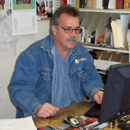
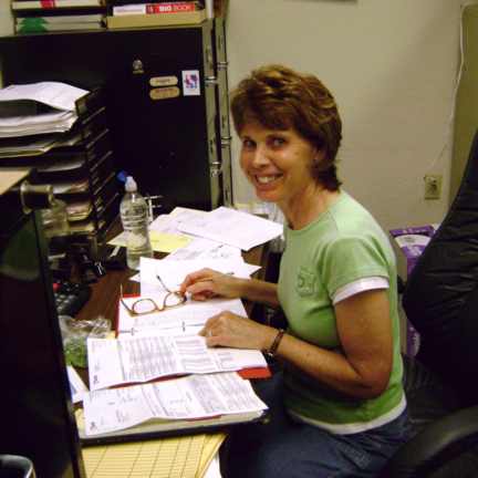
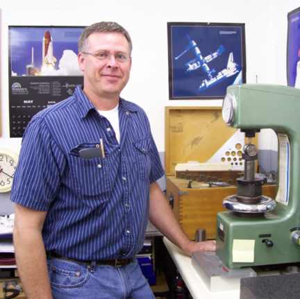
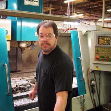
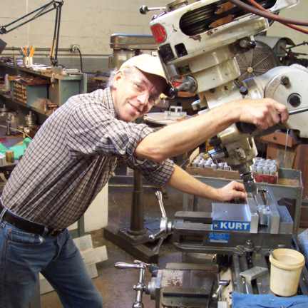
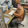
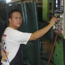
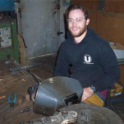
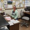
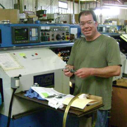
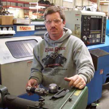
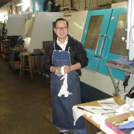
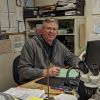
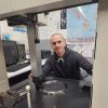
The S and S Machine Crew
|
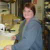
The crew at S and S is our most valuable
asset. They are highly skilled and committed to delivering top quality
parts on time. In addition to getting the job done, they are always
looking for ways to make improvements in our customers parts which can
result in either a better part or a cost savings for our customers
or both. We are also pleased at their
commitment to S and S as evidenced by their years of service. Our 28
employees have a combined total of 376 years service for an average of
just over 13 years per employee. Our plant manager, Jay Molander, has
been with S and S now for over 44 years.
|
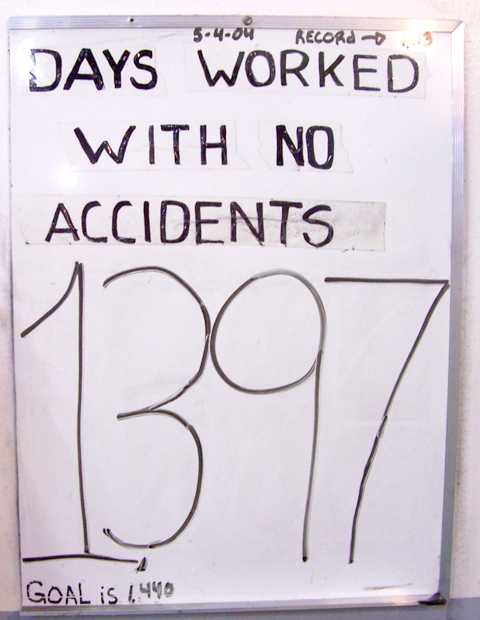
Our Safety Record
-
Our Safety Record is something we are very
proud of.
Considering the potential danger of working in a machine shop with razer sharp cutters, flying metal chips,
heavy objects, rotating machinery and potentially slippery
floors, we feel our crew is doing a great job of preventing injuries!
It is no accident that our record is so good. Everyone works hard to prevent
hazardous situations from occurring and corrects them immediately when they are
discovered. Below are three of our benchmark accopmlishments. As you
see, the duration of our accident free periods continue to increase.
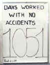
- Starting in March of 2004, we
went for 1051
consecutive days without a"Lost Time Accident" .
|
 |
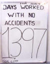
- As of March
2010 we were accident free for 1397days.!
|
 |
- We continue in or efforts to remain "lost time" accident free
and as of March 2016
we have reached an all time high for us with 1592 accident free days
and we are still counting.
|
 |
| |
|
Equipment List:
CNC Milling Equipment
·
1 Mazak
625 Multiplex with
rear load magazine bar feeder, 2 spindles each with turning & milling, 6
axis (actual photo)
·
1 Mazak Multiplex 625 Dual
Spindle CNC Lathe/Mill with bar feed, front load magazine bar feeder
·
Mazak 18MS CNC Lathe/Mill,
Super Quick Turn, with gantry robot loader, 2 spindles each with turning
and milling, 5 axis
·
1 Akira Seiki 5AX-AC650-5 5
axis Vertical Machining Center Full Simultaneous 5 axis
Travel X32” Y 23” Z 22” 500 mm rotary, High pressure through
spindle coolant
·
1 Akira Seiki V4 Vertical
Machining Center Travel: X 41” Y 20” Z 20”
28 Tools
·
2 Akira-Seiki V4.5 Vertical Machining
Centers, Travel: X 45" Y 25" Z 26" 28 tools, 25 hp, 9000 RPM
spindle, w/8" 4th axis rotary table
·
5 Akira-Seiki V5 XP Vertical
Machining Center X52.2 Y 24.6
Z 25, 24 tools
·
1 Akira-Seiki HSV 1400
Vertical Machining Center X56.6 Y30.2
Z27, 24 tools
·
1 Akira Seiki V7 Vertical
Machining Center Travel: X 66”
Y 34” Z 32” with 4th axis capability
·
2 HAAS VF2 Vertical Machining
Centers with 4th axis capability
·
2 Troyke
rotary table 15" cnc 4th
axis-horizontal & vertical for Yam 3A
·
1 Troyke
rotary table 15" cnc 4th
axis horizontal & vertical for Advanced VMC 1000
·
1 Tsudakoma
rotary table 12 ½"
cnc 4 th axis horizontal & vertical
CNC Lathe Equipment
·
1 Yam CK2 lathe with 1 3/4"
bar capacity
·
1 Femco Slant bed CNC lathe 1
¾” through spindle
·
2 Femco
Durga-25E lathes, with 32 tool, tool changer
·
2 Terry Bar bar feeders, with
2 ½" dia. x 20’ capacity
·
HAAS SL10 Turning Center
Milling Machines Manual
·
16 Bridgeport
or Bridgeport type vertical mill with
digital readout & power feed
·
2 Comet mill, vertical, heavy
duty oversize Bridgeport type
·
1 Cincinnati #2 mh mill
horizontal
·
1 Kearney & Trecker no. 2
vertical mill - 10 h.p.
Lathes, Manual
-
·
2 Hardinge chucker
with automatic threading
·
1 Hardinge chucker with
manual threading
·
3 Hardinge Tool Room Lathes
·
1 Tsugami chucker
with manual threading
·
3 Osama engine lathe, 17"x40"
25" gap
·
1 Osama engine lathe, 17"x80"
25" gap
·
1 Osama engine lathe with 60"
bed
·
2 Supermax 2660 gap bed
lathes with 26” swing x 60” between centers and 4” through spindle
·
2 Supermax 2680 gap bed
lathes with 26” swing x 80” between centers and 4” through spindle
·
1 SHENYANG S1-245B Lathe 35”
swing x 72” between centers, 9 ¼” through spindle
Turret Lathes
EDM Machines
·
1 Mitsubishi BA8 Wire EDM
·
1 Mitsubishi FA20 Wire EDM
·
1 Gromax V20-50A Die Sinker
·
1 Current EDM Hole Popper
with Auto Tool Changer
Grinders
·
1
Abrasive 8"x24" #3b surface grinder power table
·
1 Lisle drill sharpener
·
1 Clawi-Spiral drill
sharpener
·
1 Dumore
toolpost grinder
·
1 Baldor tool room grinder, 6"
·
3 pedestal grinders 6’, 8",
10"
·
1 Sunnen hone, power stroke model MBB-1800
·
1 DoAll surface grinder,
hydraulic feed 8" x 20 "
·
1 Chevalier Surface Grinder
8” x 18”
·
1 Chevalier FSG-3A 122H4
Automatic Surface Grinder 12” x 24”
·
Agathon 175-1 diamond tool
grinder
Welding Equipment
Saws
Drill Presses
- 1 Central drill press, special application
- 1 Fosdick drill press, 24"
- 1 floor model drill press #3 taper, 18"
- 1 First floor drill press, 17", #3 taper
- 2 First bench drill press, 16"
- 1 Rexon bench drill press, 14", 1/2"
- 1 Chicago bench drill press, 14"
- 9 floor drill press, 14", 1/2"
- 1 Electro-Mechano drill press, 15,000 RPM
Punch Presses
Finishing Equipment
Sheet Metal Equipment
Inspection Equipment
·
1 Mitutoyo
coordiante measuring machine,
28"x20"x15 1/2"
·
1 Mitutoyo
coordinate measuring machine,
, 20"x16"x12"
·
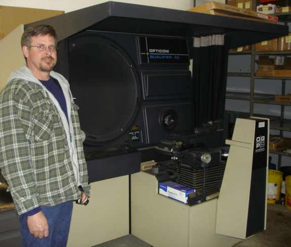
1 OGP ( Optical Gaging Products ) optical comparator 30 " with digital
readout, .0001
accuracy & 10x, 25x, 31.25x, 50x, 62.5x & 100x magnification Photo
of our machine
·
1 Micro
Vu optical comparator,
14" with digital readout & 10x & 20x magnification
·
1 J & L 30" optical comparator with 5x, 10x, 20x, 50x & 100x magnification
·
3 Stereo microscope 20x
·
1 Mitutoyo toolmakers
microscope x y travel 2" x.0001"
·
3 digital
height gage, 18" - 24" SPI and Mitutoyo
·
3 vernier height gage 18" -
24"
·
2 dial height gage, 18" - 24"
·
1 granite
master square surface plate, 14x14x3
·
5 surface plate, granite
24"x18"
·
8 Starrett surface plate, granite 36"x24"
·
1 surface plate, granite
48"x36"
·
1 Micro Flat Granite Surface
Plate 8” x 36” x 60” 4 ledge
·
1 Granite Surface Plate 12” x
36” x 96” 4 ledge
·
1 Granite Surface Plate 14” x
60” x 144”
·
1 Wilson Rockwell type
hardness tester for Rockwell c, b, etc.
·
1 Wilson hardness tester Rockwell
superficial type for Rockwell 15n 30n 45n, etc. (actual photos of our
testers)
·
3 gage
block sets (81 pc,
36 pc, 8 pc)
·
1 gage
pin set .011 - 1.000" in .001" increments
·
1 gage
pin set .001 -.750 in .001" increments
·
1 Trimos
height master, 12", with 6" master ext.
·
3 Fowler
Sylvac bore gage sets,
range 6mm – 150mm (.236 – 5.905) with 5 digital readout displays
·
1 Fowler
Bowers Sylvac bore gage set,
range 10mm – 19mm (.394 -.748dia) with digital readout
·
200+ Ring
gage standards from .0985 dia. to 5.970
·
1 Mitutoyo
micrometers set (1" to 12")
·
4 Thread
pitch micrometers (1"
to 3")
·
4 Blade
micrometers, up to 5"
·
1 36"
Mitutoyo inside mic set
·
1 Pratt
& Whitney bench type super mic
·
1 Federal Series 99P-20
groove gage
·
1 MikroTest plating thickness
gage
·
15 Chatillon
Mechanical Force Gages, ranging from 5 to 500 lbs.
·
10 Correx gram gages / Dynamometers,
ranging from .5 - 5 grams to 100 - 500 grams
·
1000+ Deltronic precision gage pins, assorted sizes
·
500+ Thread, Plug and Ring gage sets
·
misc vernier calipers to 80"
·
misc precision v-blocks to
12"
·
misc dial
indicators from Brown and Sharpe and others
·
misc precision machinist
squares up to 36"
Software/Computer
Miscellaneous
Equipment
·
2 Procunier
leadscrew tapping machines
·
2 Bridgeport vertical mill
slotter / shaper attachments
·
4 Haas 5c automatic indexing
head, programmable
·
1 8" rotary table with Haas
control
·
7 rotary tables 8", 10", 12",
15", 16"
·
1 12" universal (tilting)
rotary table "SIP" (swiss made)
·
1 8" superspacer
·
5 dividing heads 8", 10", 12"
·
1 5c indexer (Hardinge head)
·
8 Geometric die heads 3/4 - 2
1/2"
·
3 H&G die heads 0 - 3/4"
·
1 Di-Acro
#2 bender
·
3 Di-Acro
#1A benders
·
1 Jet 2 ton arbor press
·
1 Jet 3 ton arbor press
·
1 Famco
#4 arbor press
·
1 40
ton hydraulic press
·
1 50 ton hydraulic
straightening press with 48” x 84” table, infinitely adjustable gantry
type
·
1 200 ton Hydraulic Press H
Frame Sliding Gantry Type
·
1 Kellog/Comp
air rotary air compressor 30
hp
·
1 Gardner-Denver
Elecrta-Screw,
Rotary Screw Compressor, 30HP, 130 CFM, Model EBEGD
·
1 Curtis air compressor, 80
gallon 5 hp
·
1 Curtis air compressor,` 120
gallon 10 hp
·
1 Hyster 30000 # Forklift
·
1 Taylor 30000 # Forklift
·
1 Clark 25000 # Forklift
·
1 Yale 12000 # Forklift
·
1 Clark 8000 # forklift
·
1 Toyota 6000 # forklift
·
2 Toyota 5000 # Forklift
·
1 Baker 4500 # forklift
·
1 1000 # shoplifter, electric
·
1 Lucifer dual chamber heat treat furnace,
12" x 15" x 30"
·
1 Lucifer
dual chamber heat treat furnace 11" x 12" x 24" (actual photo)
·
1 Superior heat treat furnace
8" x 8" x 5" chamber
·
1 AP Lazer SN4836 100 watt
CO2 48” x 36” Table
Building
Area Served:
Although we have customers all over the US and abroad, we are
really in our element when we can work face to face with engineers. When we
get a part that is costly to produce due to a feature that is either difficult
to machine or inspect, we often talk to engineers to try and find a functional
equivalent that is less costly. That process seems to work best when we can
meet with the engineers in person and it's even better if we can get our hands
on the assembly that the part fits into. For that reason, we tend focus on our
local community. These are some of the cities that we can most efficiently
serve: Antelope, Auburn, Cameron Park, Carmichael, Citrus Heights, El
Dorado Hills, Fair Oaks, Granite Bay, Lincoln, Loomis, Marysville, Newcastle,
North Highlands, Orangevale, Penryn, Placerville, Rancho Cordova, Rocklin,
Roseville, Sacramento, West Sacramento, Woodland and Yuba City.
Contact Information
Home Page


In memory of Pete
 S and S Machine is an industrial machine shop which has been located in
Roseville, California (between Sacramento and Auburn just off Interstate 80) since
1973. More specifically, we are a CNC (computer numerically
controlled) job shop which means that we manufacture custom precision
machined parts to our customers specifications on computer controlled machine
tools. S and S Machine has about 25 employees and
over 30,000 square feet of combined shop, office and warehouse
space. We manufacture a wide range
of items such as medical equipment parts, functional test fixtures for the
electronics industry, aerospace parts, bicycle
parts, machinery parts and just about anything
else you can imagine that is machined from metal or plastic.
S and S Machine is an industrial machine shop which has been located in
Roseville, California (between Sacramento and Auburn just off Interstate 80) since
1973. More specifically, we are a CNC (computer numerically
controlled) job shop which means that we manufacture custom precision
machined parts to our customers specifications on computer controlled machine
tools. S and S Machine has about 25 employees and
over 30,000 square feet of combined shop, office and warehouse
space. We manufacture a wide range
of items such as medical equipment parts, functional test fixtures for the
electronics industry, aerospace parts, bicycle
parts, machinery parts and just about anything
else you can imagine that is machined from metal or plastic. 


